

Jaime Prat, ASK Chemicals España, S.A.
Dr. Reinhard Stötzel, ASK Chemicals, Hilden
Ismail Yilmaz, ASK Chemicals, Hilden
Copyright – 2012 World Foundry Congress
ABSTRACT
Sand additives are widely used within the foundry industry to control veining defects on cored surfaces. They are most often used in conjunction with refractory coatings which improve surface finish and control metal penetration, thus requiring two additional products and processes for high quality castings. A new product has been developed that combines the positive effects of additives and coatings into a single material. The new additive is based on low density alumina silicate ceramic (LDASC) with a small addition of fluxing material.
Testing has shown that this material has unique expansion and contraction properties that both eliminate veining and provide a superior casting surface finish. A 5% addition level is sufficient for most applications. A variety of automotive castings including disc brake rotors, brake calipers, and steering knuckles have been produced with good results without the need for coatings. This paper reviews the development of the new additive and shows the potential benefits in both quality and cost.
STATE OF THE ART
A number of different types of materials have been used as anti-veining sand additives. These include organic materials like wood flour, starch/dextrin, and seacoal (powdered bituminous coal). These organic materials are effective against low levels of veining, but they also increase gas evolution and can contribute to metal penetration by leaving gaps between the sand grains after they burn away.
Inorganic materials are also used as silica sand additives or replacements. These can include other aggregates like zircon or chromite sand, fused silica, or man-made aggregates that have inherently lower expansion rates than silica sand. These are typically used at relatively high percentages and can greatly increase raw material costs.
Fluxes, or materials that react with and soften the surface of the silica sand, have also been used successfully. Red and black iron oxides and other metal oxides have been used for several decades.
Other “Engineered Sand Additives” (ESA’s) have been developed more recently. These seem to rely on the fluxing properties of naturally occurring minerals like spodumene (a lithium ore), illmenite (a titanium ore), alkali carbonates, or on processed minerals that contain fluxing agents. These have an advantage in that they are effective in severe applications and can be used at relatively low levels (typically 2 – 8%). A potential disadvantage is that they are often mildly basic before use and can become very basic after exposure to elevated temperatures. This can negatively impact many common binder systems. Another disadvantage is that they can interact with the liquid metal and modify the surface tension, thus causing increased metal penetration and poor surface finish.
Another ESA (ASK ISOSEAL™ 2000, i.e. “2000”), described in the European Patent 0891954, is based on a completely different principle. This ESA contains low density aluminum silicate ceramics that collapse or deform during heating, offsetting the expansion of the silica, but in turn create a barrier to metal penetration. It has minimal effects on sand and metal chemistry and actually improves casting surface finish. Figure 1 shows a micrograph of the mixture of sand and LDASC.
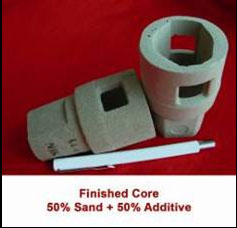
The ESA 2000 also provides some very special thermal properties. When used at levels up to 50% by volume (20% by weight) it can modify the thermal properties of the sand mix to improve feeding and prevent shrinkage, while simultaneously preventing veining and providing good surface finish without coatings. Also, during the use of the additive for the production of the cores with 50% sand and 50% additive, it was determined that there was no need for coating (Figure 2).
The problem with the ESA 2000 additive is that when used at levels less than 10% by weight in the sand mixture, it does not always completely prevent veining. On the other hand, if a high percentage of 20% is used, the problem becomes extremely expensive to solve. There was a need to develop an LDASC based additive than can be successfully used below 10%.
DEVELOPMENT METHODOLOGY
An effort was started to develop a new sand additive based on LDASC technology that could prevent veining at lower levels, but maintain the good surface finish without a coating. Initially, tests were conducted to characterize the chemical and thermal properties of a number of different LDASC raw materials. Properties for characterization are shown in Table 2.
Table 2: Properties for testing
| Chemical | Thermal |
|---|---|
| Initial Contraction Temperature |
| Final Contraction Temparature |
| Softening Temparature |
| Sphere Temparature |
| Hemi-Sphere Temperature |
| Fusion Temperature |
|
Once the different LDASC options were defined, their chemical compositions were analyzed (Table 3). Large variations in both the alumina content and the amount of impurities were found.
Table 3: LDASC compositions by weight %
| Sample 73 | Sample 74 | Sample 75 | Sample 76 | Sample 76 | |
|---|---|---|---|---|---|
| Al2O3 | 28,8 | 16,7 | 27,8 | 30,2 | 38,2 |
| Fe2O3 | 6,4 | 4,09 | 4,66 | 3,76 | 1,91 |
| CaO | 0,75 | 2,02 | 1,85 | 2,41 | 0,96 |
| MgO | 1,55 | 1,51 | 0,97 | 1,29 | 0,4 |
| Na2O | 0,43 | 0,9 | 0,58 | 0,21 | 0,35 |
| K2O | 4,36 | 3,92 | 2,25 | 2,14 | 0,57 |
| TiO2 | 1,39 | 0,79 | 1,04 | 1,99 | 1,07 |
The thermal testing was carried out in a Misura heating microscope. The heating microscope is a device that allows visual recording of a sample during a heating cycle. The silhouette of the sample is recorded on a computer during the fusion test. From the recorded images, the evolution of the contraction of the sample can be determined as a function of the temperature, using image analysis equipment.
Each sample was formed by pressing a cylindrical button 3 mm in diameter and 3 mm in height, which was placed on a stand. This stayed in the instrument sample holder of the heating microscope where it underwent heating at a rate of 25°C/min, (77°F/min) to the maximum temperature of 1550º C (2822° F).
From the recorded images, the contraction temperature curve was plotted and the following characteristic temperatures were determined:
- Initial Contraction Temperature, when the area of the silhouette of the sample was 99% of the initial area of the same
- Final Contraction Temperature, when the sample stopped contracting
- Softening Temperature, when the edges of the sample began to round
- Sphere Temperature, when the profile of the sample took the form closest to a sphere
- Hemi-Sphere Temperature, when the sample took the form closest to a hemi-sphere (half sphere)
- Fusion Temperature, when the sample took the form closest to a rounded cap, equivalent to ~1/3 the volume of a sphere.
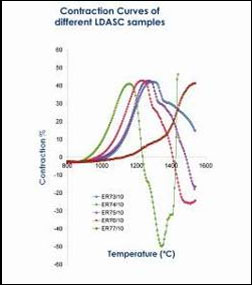
Figure 3 and Table 4 show the results of the Misura thermal analysis:
Table 4: Thermal Analysis of the LDASC Samples
| Typical Temperature | Sample 73 | Sample 74 | Sample 75 | Sample 76 | Sample 77 |
| Initial Contraction Temperature r | 1045 C | 935 C | 1025 C | 990 C | 1155 C |
| Final Contraction Temperature | 1295 C | 1160 C | 1270 C | 1235 C | 1550 C |
| Softening Temperature | 1340 C | 1250 C | 1445 C | 1355 C | ---- |
From here we compared the chemical properties of the LDASC materials with the Initial Contraction Temperatures (Figure 4). Veining tests were also performed on 2x2 test pieces (2 inch diameter by 2 inch height) to determine if there was any relationship between veining and the thermal characteristics. Each core sample contained 5% LDASC and 95% silica sand (Figure 5).
Table 5 includes the relationship among them. It shows that as the initial temperature of contraction decreases, the tendency for veining is less. In addition, the Na and K impurities act as a flux on the sand, resulting in greater penetration and poorer surface finish. Figure 6 shows the final profiles for the different samples after Misura testing.
Table 5: Comparison of Initial Contraction Temperature and Veining
| Typical Temperature | Sample 73 | Sample 74 | Sample 75 | Sample 76 | Sample 77 |
| Initial Contraction Temperature | 1045 C | 935 C | 1025 C | 990 C | 1155 C |
| Veining Rating | 10 | 6 | 10 | 7 | 10 |
Next, our research turned to the influence of different types of fluxes on the samples. After several trials with different types of fluxes, it was found that 6% Li2CO3 in Sample 77 gave similar Initial Contraction Temperatures. However, the Final Contraction Temperature was lowered by 230ºC (446°F), so that the contraction would be much faster during casting. Lithium carbonate was also added to LDASC 73 for comparison (Table 6).
Table 6: Effects of Li2CO3 addition to Samples 73 & 77
| Sample 77 | Sample 73 + 6% Li2CO3 | Sample 77 + 6% Li2CO3 | |
| Initial Contraction Temperature | 1155 C | 1085 C | 1215 C |
| Final Contraction Temperature | 1550 C | 1210 C | 1320 C |
| Softening Temperature | 1240 C | 1335 C | |
| Fusion Temperature | 1295 C | 1350 C |
The resulting contraction curve for Sample 77 with 6% lithium carbonate (Sample 98) is shown in Figure 7.
Similarly, Misura Thermal Analysis was used to develop the curves for sub-angular and round sand (Figure 8) and for other mineral additives in sand for comparison (Figure 9).
Observing that the behavior of sample 77 with 6% Li2CO3 came closest to the curves with other sand additives that were effective against veining, samples to evaluate the veining and penetration were prepared for the new additive (now designated ISOSEAL™ 2011 or ESA 2011).
CASTING TESTS
Cores were prepared using 94% sub-angular sand C-70, 1.5% phenolic urethane binder 418/618, and 5% of the ESA 2011 additive (94% of sample 77 LDASC + 6% Li2CO3). The 3 components were mixed in a mill and loaded into the hopper of a core blower. The mixture was blown into the core box to obtain the core shape and then gassed with DMEA. The cores were ejected and used for the subsequent casting tests.
The 2x2 cores were placed in the molds and poured with grey iron. The castings were cleaned and the veining and surface finish (SF) were rated on the scale of 0 – 10. Table 7 shows the results.
Table 7: Casting Test Results
| Mix | 100% Sample 77 | 94% Sample 73 + 6% Li2CO3 | 94% Sample 77 + 6% Li2CO3 | 94% Sample 74 + 6% Li2CO3 | 94% Sample 74 + 6% Li2CO3 | 100% Sand |
| % Added to sand | 10 | 5 | 5 | 3 | 5 | 0 |
| Veining Rating | 7 | 0 | 0 | 1 | 0 | 10 |
| SF Rating | 1 | 0 | 0 | 0 | 0 | 0 |
It was noted that 6% lithium carbonate as a component of the anti-veining additive produced no veining, regardless of the sample of LDASC used. Also, the castings all exhibited an excellent surface finish.
By contrast, the samples from cores without additives (100% sand) and the samples with LDASC alone as the additive, produced significant veining defects of 10 and 7 respectively (on a scale of 0-10 for veining, being “0” the best and “10” the worst).
Subsequently both the effects of lithium carbonate levels in a LDASC based additive of sample 77 and the amount of additive in the composition of the molding sand were tested. The results are shown in Table 8.
Table 8: Sample Compositions and Casting Results
| SAMPLE | 115 | 116 | 46 | 49 | 80 |
|---|---|---|---|---|---|
| 70 AFS GFN SAND | 95% | 97% | 95% | 90% | 100% |
| Additive | 5% | 3% | 5% | 10% | 0% |
| Additive Composition | |||||
| Li2CO3 | 6% | 6% | 0% | 0% | 0% |
| Sample 77 | 94% | 94% | 100% | 100% | 0% |
| Casting Results | |||||
| Veining Rating | 0 | 1 | 8 | 7 | 10 |
| SF Rating | 0 | 0 | 1 | 1 | 0 |
Next, testing was conducted to compare the chosen additive with the other two inorganic additive systems mentioned above (Figures 10, 11 and 12).
Once confirmed that the results were satisfactory, we moved to perform industrial testing focusing first on foundries that use 70 AFS GFN sand, which is the common practice for vertical molding, and we then continued the testing with other, coarser sands (Figures 13, 14, 15, 16, 17, 18 & 19).
All the tests were satisfactory with the sand used in the foundries. The exception is shown Figure15. For brake disks, using AFS GFN 55, some veining and penetration was seen. Once the sand was changed to AFS GFN 65, the problems were corrected.
Effect on the bench life
At higher temperatures, the additive increases the acid demand value (ADV) of the mixed sand, which decreases the bench life. This can be addressed using binder 419/619, a cold box binder that has greater bench life (Figure 20).
Gas Evolution
The ESA 2011 additive does not produce additional gas evolution compared to sand alone (Figure 21).
Effect on Core Density
Additions of 5% of ESA 2011 additive decrease the weight of the core by about 10%. This means more cores can be produced from the same weight of mixed sand and that the cores are lighter and easier to handle.
Effect of the Additive on Green Sand
A laboratory study was conducted simulating the effects of burning the core and charring the additive and adding it to the molding sand at a rate of 2.5%. No effect was observed (Table 8 and Figure 21).
Table 9: Greensand properties with 2.5% burned ESA 2011
| Bentonite | Geko S | Geko S |
| Sand | LA 32 | LA 32 |
| Additvie | Without Additive | 2.5% Burned Additive |
| Water Quantity (g) | 63 | 70 |
| % Water | 1.7 | 1.77 |
| Compactability | 46 | 46.5 |
| Permeability | 220 | 215 |
| Green Shear kPa | 3.2 | 3.10 |
| Green Compression kPa | 102 | 100.0 |
| Weight of Sample (g) | 149 | 145.5 |
CONCLUSIONS
- It is possible to produce vein-free automotive castings without coating by using additions of the new ESA 2011 additive. Sand grain size is critical for up to 500 mm of Ferro static pressures, but the particle size is not as critical with lower Ferro static pressures.
- Best results were obtained with additions of 5% of the new ESA 2011 additive with 65/70 AFS GFN sand.
- Satisfactory results have been produced with chromites mixtures on large cylinder heads. This opens the possibility of producing cores for both cylinder blocks and cylinder heads without the use of a coating. This is provided along with the enormous technical and competitive advantage that is gained when the scab defects associated with coating and the blow holes associated with low permeability and gas evolution disappear.
REFERENCES
- US Patent 4735973
- European Patent 0891954
- Spanish Patent 2116245
- J. Prat, L. Iglesias, M. Arrieta, I. Landa, A. Meléndez, E. Anglada, A. Beeson, J. Barcena, “New Casting Solutions: Numerically Simulated Exactcast™ Core-Sleeves Eliminate Critical Problems With Automobile High-Security Components (Patented) 2004 WFC, Istanbul, Turkey
- J. Prat, M. Arrieta, J. Galaz, A. Meléndez, A. Seoane, E. Anglada, A. Beeson, A. Jorge, T. Vicario, “Improving Casting Performance Through Customized Insulating Shapes And Advanced Simulation Techniques” 2006 WFC Harrogate, UK
- W.L. Tordoff, R.D. Tenaglia, “Test Casting Evaluation of Chemical Binder Systems,” AFS Transactions 2007
- Showman, R., Horvath, L., Clifford, S., Harmon, S., Lawson, E., “A Systematic Approach to Veining Control,” AFS Casting Congress Proceedings, 11-005
- European Patent 027700038
also available in <link record:tt_news:12207 internal-link>
![]()
###COMPANY_LINK### <link record:tx_browserdirectory_directory:235 internal-link>ASK Chemicals GmbH