
Abstract: To introduce the development method, performance values and results newest generation of the integrated high-efficiency heater for the core machines, as well as a finite element analysis method to improve the performance of the heater, with an integrated design concept.
The results show that significant results have been achieved in improving the curing efficiency of the core making machine, reducing energy consumption and creating catalyst material savings.
1. Introduction
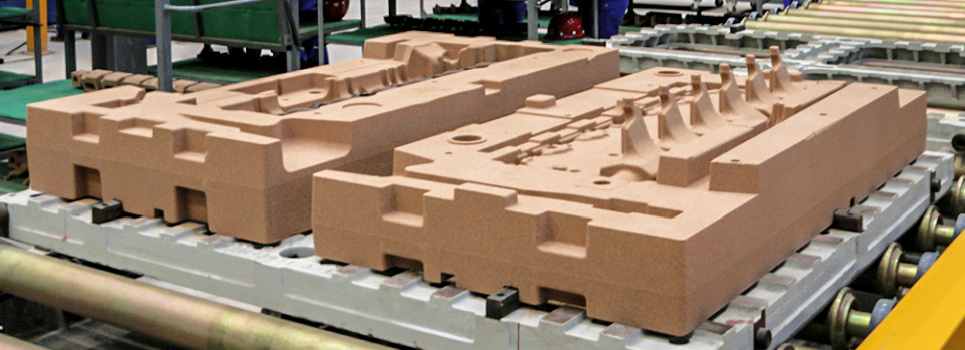
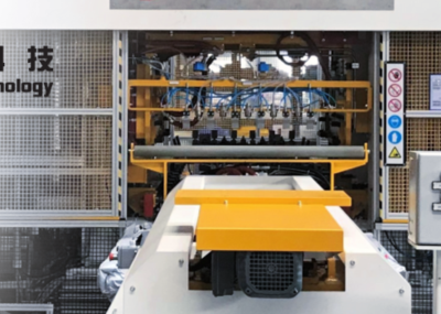
The gas generator (including gas heater, abbreviated as heater) of the traditional core making machine, widely used in the foundry industry, is usually installed separately from the equipment. Its main function is to send high-temperature gas or catalytic gas into the blowing plate through hoses, joints, the connecting plate,and into the core box, resulting in the hardening of the sand core.
Based upon research into the inorganic and organic core curing process, improving the heater's ability to continuously provide high-temperature gas is a known challenge. Considering the status quo and inherent problems, the development of high-performance heaters can provide high-level efficiency and energy savings.
With the current technology, the high-temperature gas has a lengthy transport distance, great temperature loss (up to 60% or more), high energy consumption, and poor stability. Especially among the conditions of the inorganic curing process, the temperature cannot be guaranteed, resulting in low curing efficiency and high energy consumption.
2. Status analysis
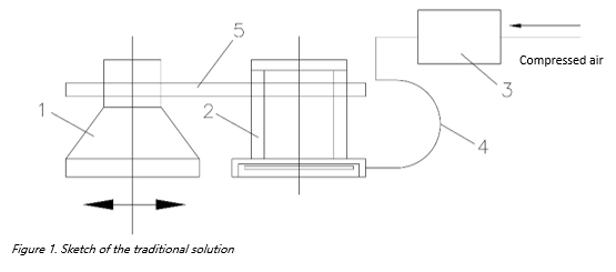
The schematic diagram of the traditional generator scheme is revealed in Figure 1, which shows the combination of the upper moving mechanism of the core making machine. Since the upper part of the core making process repeats once every cycle, the heater is fixed on the upper frame, and the hot air or the catalytic gas is delivered to the gassing bell under a specific pressure which results in the hardening of the sand core.
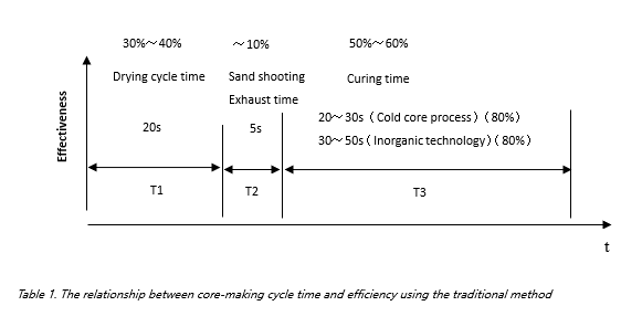
For analysis of the cycle time of the core making process, we use the 40L core-making machine core cycle time as an example; see Table 1
T1-The time required for auxiliary equipment actions in core making (s).
T2-The period of time for sand shooting and discharge of high-pressure gas after the mold closing equipment is locked (s).
T3- The time required for core sand curing after filling the cavity (s)
The core-making cycle time is T=T1+T2+T3, and the hardening of the sand core accounts for about 50%~60% of the core-making cycle. The traditional core-making efficiency is about 50-60 type/H (cold core process), 40-50 type/H (Inorganic technology).
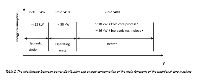
For analysis of the distribution power composition of the main functions of the core making machine, we use the 40L core making machine as an example, see Table 2:
The main functional power distribution of the core making machine is divided across the hydraulic station (pressure), operating units, and heaters. Among these, heaters account for about 25%~40%. Combined with the previous evaluation data, the curing energy consumption of the traditional core making machine(Cold core process) is about 0.009Kwh/kg(Calculated based on the ratio of the measured curing energy consumption to the weight of the sand core during a specific blowing period).
3. Integrated solution
3.1 According to the above analysis of the operating cycle, the heater accounts for 60% of the total core-making cycle, and the energy consumption accounts for 40%. The question of how to integrate the design will be the starting point in a addressing the efficiency and consumption problem.
- The heater integration task includes primarily structural integration and functional integration.
- Structural integration: the heater is integrated with the blowing hood of the core making machine.
- Functional integration: heater and cold core process catalyst atomization accomplish a functional integration.
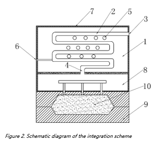
The schematic diagram of the integration scheme is shown in Figure 2
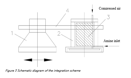
The schematic diagram of the integrated scheme is shown in Figure 3. Compared to the traditional scheme, the other mechanisms are the same, but the heater is integrated on the blowing hood, eliminating the traditional connecting hose assembly.
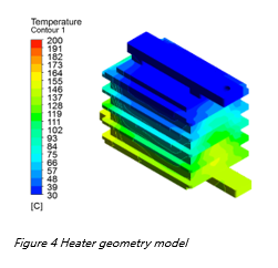
3.2 According to the current structure of the key functional component of the heater, its physical shape and the geometric model of the fluid channel area are preprocessed, and the flow and heat exchange process of the heater are simulated and analyzed according to the operating conditions of the heater.
Figure 4 - Heater geometry model
1) The three-dimensional flow trajectory diagram of the gas in the heater channel and the core area diagram of the air flow vortex are obtained through simulation, and the air inlet Reynolds number, obtained through simulation, is within the “strong turbulence” stage.
2) The heater is designed to simultaneously introduce gas into both sets of flow channels. Since the channel geometric structure is symmetrically similar, the gas flow in the two sets of flow channels also exhibits a symmetrically distributed flow pattern.
3) It can be seen from the schematic diagram that within the heater flow channels, the gas flow state in most areas is a turbulent vortex flow, so the heating and heat exchange efficiency of the heater is relatively high.
4) The serpentine curved flow channels in the different layers of the heater are connected through the vertical tube. Due to the small size of the round tube, the acceleration of the gas flow is achieved by the constant scaling of the pipe size in the heater, which enhances the heat exchange effect to some extent.
5) From the top inlet of the heater to the bottom outlet, the temperature rise of the gas is relatively stable and continuous. This indicates that when the heating rod is working, the heater shell and the gas near the boundary layer near the wall of the flow channel are effectively heated, and the vortex in the elbow area makes the gas heat exchange stronger. The temperature rise of the mainstream in the smooth straight channel depends primarily upon the heat status of the molecules.
4 Production test and verification results
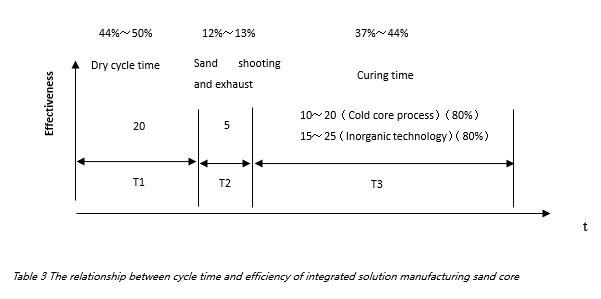
4.1 Through the application of the integrated solution, due to the increase of blowing temperature and continuous improvement, the blowing curing time is significantly shortened, thereby reducing the amount of sand core curing time and improving the core making efficiency. (See Table 3)
The percentage of sand core hardening in the core-making cycle is reduced from 50%~60% to about 37%~44%, and the core-making efficiency of the integrated solution is increased to approximately 90-100 type/H (cold core process) and 80-90 type/H (inorganic process).
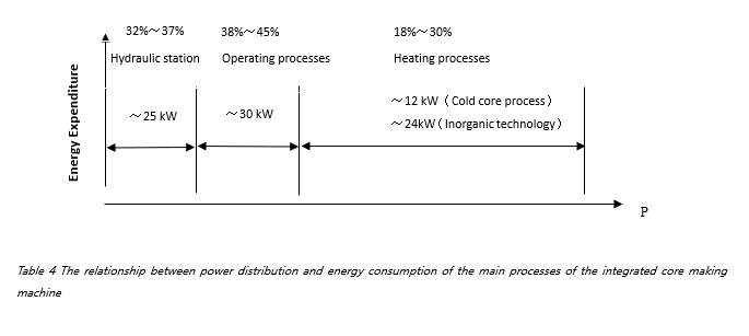
4.2 Due to the elimination of the high-temperature gas delivery pipeline, the blowing temperature heat loss is greatly reduced, while the same inlet temperature of the blowing hood is achieved. The set temperature of the heater integration scheme is lower, the response time is shorter, and the percentage of heating power is also reduced from 25%~40% to 18%~30%. In addition, the curing energy consumption is estimated to be reduced by more than 50%. (See Table 4)
In addition, for the cold core process, as the heater and the catalyst atomization are functionally integrated, the catalyst can be blown and injected after the initial atomization, and the catalyst gasification efficiency and utilization rate are improved, thereby reducing the catalyst. In the case of consumption, a higher catalytic effect is obtained, and the curing efficiency is improved.
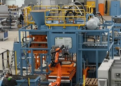
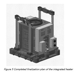
4.3 Figure 5 represents the finalized plan of the integrated heater, which has been applied to the production test verification of the Mingzhi MiCC300 integrated intelligent core-making unit. Almost 200,000 molds of sand core have been manufactured with no process failures. The blowing inlet temperature of the organic process can be above 150℃. Inorganic process blowing inlet temperature is above 200℃ (blowing pressure is 3bar, blowing flow is about 1200L/min);
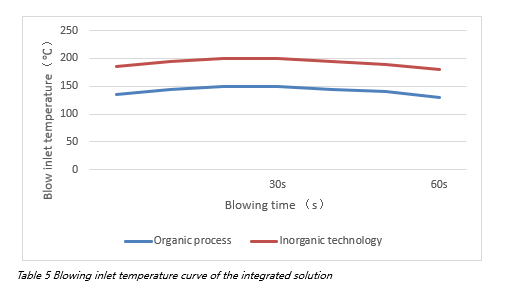
4.4 Table 5 shows the blowing inlet temperature curve of the integrated solution. During the entire high-efficiency curing period (within 30s), the blowing inlet temperature of the integrated heater shows improved capability to remain constant. The blowing inlet temperature over 30s shows a downward trend, with a decrease of about 5 %, which reflects that the heater's heat capacity, heating power and other parameters are well designed and result in good performance.
4.5 See Table 6 for verification results
The data obtained through the production test verification clearly shows: in the case of reducing the heat loss by 50%, the energy consumption can be effectively reduced by 50%, the curing efficiency increased by 30% to 50%, the amount of catalyst reduced by 30%, and the costs of exhaust gas purification treatment will decrease accordingly (the exhaust system processing air volume is reduced by 40% to 50%).
5. Conclusion
This paper studies the high-efficiency blowing and curing technology of the core-making machine. It integrates heat exchange principles, curing process principles, and advanced integrated design concepts. A finite element digital analysis model of the heater is established. Through multi-dimensional analysis, the finalized heater is also established. Design parameters, and likewise, test quantification and production verification of the finalized heater yield the following results:
(1) Reduced energy consumption by more than 30%
(2) Reduction in the amount of catalyst by more than 30% under the organic process
(3) Curing efficiency increase by about 50%
(4) Exhaust gas treatment air volume reduction by more than 50% under the organic process conditions
For questions or information: www.mingzhi-technology.com or www.mingzhi-technology.eu

