
Horizontally parted, flaskless moulding systems based on Matchplate technology have been around for many years. Outside Europe they are one of the most popular moulding processes. A general description of the technical basis of this process was first introduced in issue 08/2010 of the magazine GIESSEREI, and a moulding machine using Matchplate technology was presented to the foundry community at GIFA 2011. This paper will thus be limited to an introduction to the general plant concept.
The paper covers the following:
- Introduction to the moulding process
- Product options
- Introduction to DISA MATCH 28/32
- technical process parameters
- practical examples
- Mould hardness measurements
- at a customer foundry
- in our factory, inside and outside the chamber
- Machine-related mismatch
Introduction to the Matchplate moulding process
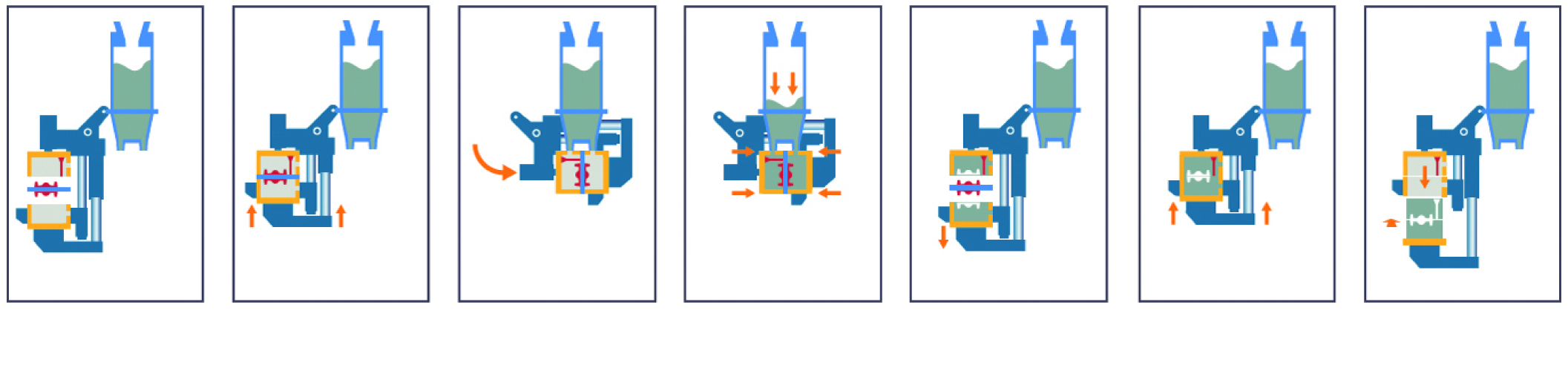
A computer animation introduced once again the entire moulding process from mould production through core setting, placement of jackets and weights and cooling to mould removal. This paper uses figure 1 below to illustrate this process.
Figure 1: The Matchplate moulding process
Product options
Table 1 shows the mould sizes available at the time. The continuously adjustable mould height contributes to an optimisation of sand consumption and a more even load on the sand plant.
Plant type | Mould width (mm) | Mould depth (mm) | Mould height (mm) UK | Mould height (mm) DK | Max. mould thickness (mm) | Max. mould weight | Mould speed/h | |
Un-cored | Cored | |||||||
DISA MATCH 20/24 | 508 | 610 | 150-200 | 150-200 | 400 | 186 | 160 | 120 |
DISA MATCH 24/28 | 711 | 610 | 180-255 | 180-255 | 510 | 332 | 120 | 100 |
DISA MATCH 28/32 | 813 | 711 | 225-300 | 225-350 | 650 | 564 | 100 | 80 |
DISA MATCH 32/32 | 813 | 813 | 225-300 | 225-300 | 650 | 644 | 100 | 80 |
Table 1: Mould sizes in horizontally parted, flaskless moulding systems
Introduction to DISA MATCH 28/32
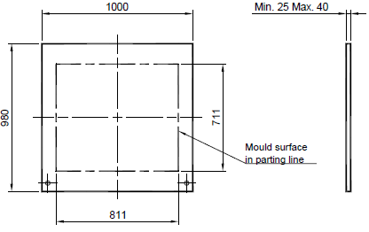
The Matchplate process employs pattern plates with patterns mounted on both sides. The dimensions 28” x 32” (711 x 813 mm) indicate the dimensions of the pattern plate in the parting line of the mould. As the mechanism for guidance of the pattern plate into the moulding machine lies outside the mould area, this is made bigger (see Figure 1). This enables Matchplate patterns designed for another machine to be employed using an adapter frame.
Figure 2: The pattern plate
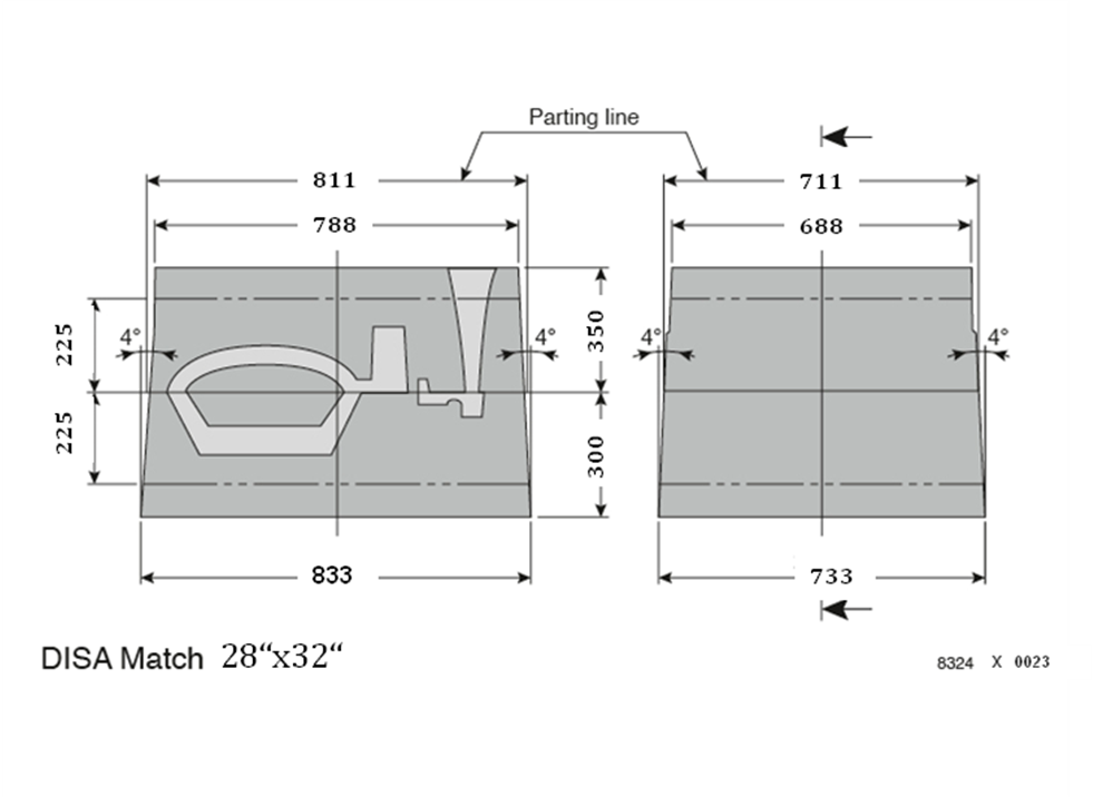
The pattern can be ventilated through the pattern plate.Figure 3 shows the dimensions of both COPE and DRAG moulds. The moulding machine is working with “mould push out” principle. This means that in the area of minimum mould thickness of 225 mm in each case both moulds have a conicity of 4° in order to facilitate an error-free edge of the mould out of both chamber flasks. The flexible areas of the mould heights from 225 to 300mm (COPE) and 225 to 350mm (DRAG) work in parallel in order to enable free height adjustment of the squeeze plate. The available top surface of the mould is reduced correspondingly; therefore placement of the pouring cup (downsprue position) and ventilation holes is possible in an area of 688 x 788 mm.
Figure 3: DISA MATCH 28" x 32"
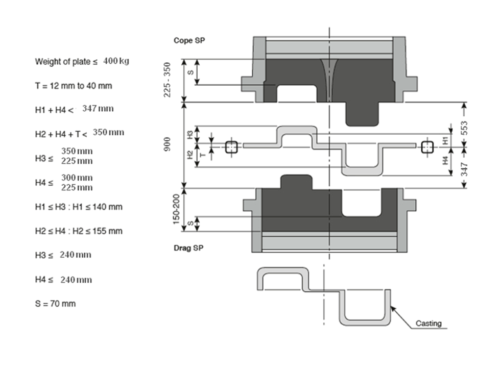
Figure 4 shows the available heights, thus defining the following measurements:H1: Distance of the DRAG-pattern plate surface from the lowest point of the DRAG-plate side H2: Distance of the COPE-pattern plate surface from the lowest point of the COPE-plate sideH3: Distance of the COPE-pattern plate surface from the highest point of the COPE-sideH4: Distance of the DRAG-pattern plate surface from the highest point of the DRAG-sideT: Patten plate strengthS: Safety distanceThe following limitations are thus determined:Maximum distance of the DRAG side from the pattern top to the DRAG chamber: H1+H4Maximum distance of the DRAG side from the pattern top to the COPE chamber: T+H2+H3S is the safety distance between the pattern and the squeeze plate, thus avoiding destruction of sand grains. This distance is normally 70 mm, but can be reduced to 60 mm if a larger pattern area is not being used:S = 70 (60)The pattern heights H3 and H4 are limited by S:H3≦(max. mould thickness) – SH4≦(max. mould thickness) – S In order to avoid a collision between the mould and the pattern, H1 must be smaller than H3 and H2 smaller than H4.
Figure 4: Available heights
Figure 5 shows the position of the pattern plate in the mould chamber. After bringing together both mould chambers with the pattern plate the system is turned 90° round its pivot to face the sand hopper. Thus the system is similar to a double DISAMATIC mould chamber. The position of both sand shot slots is designed to give optimal distribution of sand during the sand shot and also to avoid undue wear of the pattern. The depth of the mould chamber is calculated to achieve maximum mould thickness after a 25% Compressibility.
Figure 5: Position of the pattern in the mould chamber
Flaskless moulding processes are constantly associated with low pattern plate utilisation and larger edge distances (compared to flask line technology).Figure 6 should put an end to this discussion once and for all. The main thing is to ensure a stable mould surface to avoid the mould to collapse. An adequate safety distance should also be ensured in order to avoid mould breakages. Assuming a total pattern height of 200 mm with a casting module of 0.6 mm, a tight-fitting jacket enables a distance to mould edge a of around 61 mm and to mould edge b of around 80 mm. These values are proposed by the plant supplier.In iron foundries in particular there is another important factor in this context — the sand to iron ratio. A ratio of 5:1 or greater should be aimed at in order to avoid undue impact on mould quality. Constant metal/sand ratio can be facilitated by the possibility of height adjustment of the COPE and DRAG mould.
Figure 6: Edge distances
Mould hardness measurementsThe Benton Foundry in Pennsylvania uses DISA MATCH moulding machines. In September 2011 they made mould hardness test using an active pattern in the production process. Rather than performing a scientific series of experiments, the aim was simply to collect values from practice in a representative test. A mould was measured at 15 points in the upper and lower blocks. In the subsequent moulding process measurements were repeated in a random check manner in the same position. The mould hardness remained extremely constant, varying only at one point in 80 per cent of measurements. The measurement points were situated about 2 to 3 cm from the mould edge.Figure 7 shows both sides of the pattern used in the test. As in most patterns sand shot pressure of 2.0 kp/cm2 and a squeeze pressure of between 4.0 to 4.5 kp/mm2 was used.
Figure 7: Pattern sides used in test at Benton Foundry
Figures 8 and 9 show the individual measurement points on the moulds. A Ridsdal-Dielrt Green Hardness B Scale was used to test the mould hardness. This mould hardness scale was developed in the United States where moulds are generally softer as in jolt-squeeze and matchplate machines. Thus pure matchplate foundries use this scale, although the C scale is normally used to measure mould hardness from 85 and higher.
Figure 8: Mould hardness measurement points Figure 9: Mould hardness measurement points
1= 88 ≈ 6,0 | 2= 88≈ 6,0 | 3= 89≈6,2 | 1 =87 ≈5,5 | 2 =90 ≈6,5 | 3 =87 ≈5,5 | |
4= 90 ≈ 6,5 | 5= 93≈ 8,5 | 6= 90≈6,5 | 4 =90 ≈6,5 | 5 =92 ≈7,1 | 6 =90 ≈6,5 | |
7= 88 ≈ 6,0 | 8= 90≈ 6,5 | 9= 97≈14,3 | 7 =88 ≈6,0 | 8 =88 ≈6,0 | 9 =88 ≈6,0 | |
10=87≈ 5,5 | 11=97≈14,3 | 12=90≈6,5 | 10=88≈6,0 | 11=97≈14,3 | 12=92≈7,1 | |
13=87≈5,5 | 14=95≈10,8 | 15=90≈6,5 | 13=88≈6,0 | 14=96≈12,5 | 15=94≈9,9 |
Table 2: Values obtained at individual measurement points stating measured value and conversion to N/cm2
Table 2 shows values obtained at individual measurement points according to the Dielert B scale and converted to N/cm2. The squeeze pressure of DISA MATCH can be continuously adjusted between 3.0 and 10.0 kp/cm2, and shot pressure continuously adjusted between 0 and 4.5 kp/cm2. Thus the pressures used by the foundry lie in the lower region of recommended settings. The success of the foundry however lies not in the production of moulds. Figures 10 and 11 show castings after shot blasting without further finishing. The extremely clean parting lines are worthy of particular note.
Figure 10: Matchplate casting from Benton foundry Figure 11: Matchplate casting from Benton Foundry
As a result of the practical tests described above, a series of mould hardness tests was performed at our facility in Copenhagen, Denmark using a DISA MATCH 24/28 that was about to be shipped. The aim on the one hand was to test mould hardness with a shot pressure of 3.0 kp/cm2 and a squeeze pressure of 8.0 and 10.0 kp/cm2 respectively. At the same time, however, we also wanted to determine the effect on mould hardness outside the chamber flasks. The test was made using an even pattern plate and mould thickness of 190 and 255 mm in order to test the effect of variable mould heights as well.On DISA MATCH it is possible to open the mould again even after mould close up, as long as the moulds has not been pushed out of the chamber flasks. If you want to measure the mould hardness in the COPE mould it has to be separated from the DRAG mould. During the separation of the COPE mould you have to lift it and turn it. This, however, damages the mould consistency. This is why hardness measurements are made only on the DRAG mould.The test was performed as follows:
- Mould test directly in front of the moulding machine (compacatability: 40%± 2%)
- Mould production (shot/squeeze)
- Mould hardness measurement in the chamber flask
- Machine combines the moulds and push them out
- Machine finishes a new mould package that is not measured
- The mould is pushed on to a conveyor belt
- The mould is opened by hand on the conveyor belt
- Mould hardness is measured
This test was repeated three times with the same shot and squeeze pressure for both measurements. The mould sand was checked and for each test.Starting 40 mm from the mould edge, 25 measurement points were distributed evenly over the mould surface using a template that was placed on the moulds in order to ensure a constant measurement position (Figures 12 and 13).
Figure 12: Mould hardness measurement points Figure 13: Mould hardness measurement points
After mould hardness had been measured in the chamber flask, the mould was removed and destroyed. The next mould was produced, pushed out and taken apart again outside the machine. This was repeated three times with a shot pressure of 3.0 kp/cm2 and a squeeze pressure of 8.0 kp/cm2 with a mould thickness of 190 mm. The process was then repeated again three times with a shot pressure of 3.0 kp/cm2, a squeeze pressure of 10.0 kp/cm2 and a mould thickness of 190 mm. Finally the same test was made again with a shot pressure of 3.0 kp/cm2 and a squeeze pressure of 10.0 kp/cm2 with a mould thickness of 255 mm.
Figure 14: Hardness measurement outside the frame Figure 15: Hardness measurement outside the frame
Table 3 summarises the results from the test series. A considerably higher squeeze pressure was used in contrast to production at the American foundry, obviously resulting in a correspondingly greater hardness. Whether or not this mould hardness is necessary for the production of high-quality castings is a question to be answered from case to case. Basically, however, this type of hard mould can be produced. The terms “softer” and “harder” should pertain to the condition of the mould after it has been pushed out. The difference in mould hardness inside and outside the moulding machine falls within the tolerance of the measurement. Stability remains stable after leaving the moulding machine. In order to achieve further stabilisation the moulds are mounted with a jacket in the parting line area prior to pouring, the jacket stays mounted on the mould during the solidification process. In iron foundries in particular, but also in most aluminium foundries, a mould weight is placed on top of the mould. This ensures a near net shape casting in the same way as in any other automatic moulding processes.
Test | Mould thickness | Shot squeezeure | Squeeze squeezeure | Average hardness | Diff. | ||
In flask | Outside | ||||||
1 | 190 | 3 | 8 | 19,1 | 18,9 | -0,2 | softer |
2 | 190 | 3 | 10 | 22,0 | 21,6 | 0,4 | softer |
3 | 255 | 3 | 10 | 20,8 | 20,2 | -0,6 | softer |
4 | 190 | 2 | 8 | 21,3 | 20,5 | -0,8 | softer |
5 | 190 | 2 | 8 | 19,6 | 20,2 | 0,6 | harder |
Table 3: Summary of mould hardness test results in Copenhagen
On DISA MATCH you can also insert chills and risers into the mould. Figures 16 to 18 are examples from iron and aluminium foundries.
Figure 16, 17, 18
Machine-related mismatchWhile dimensions and speeds of the various moulding machines vary, one thing is always the same – the machine-related mismatch of maximum 0.25 mm that is a DISA hallmark. But what does this mismatch actually mean? The foundry lexicon offers this definition: “Defects in finished castings that can arise from an imprecise fit between parted patterns, moulds and core boxes. This gives rise to steps in the mould parting line”. (See Figure 19.)
Figure 19: Mismatch shown as steps in the parting line.
What are the reasons for machine-related mismatch (in general)?The following are possible:
- Malformed pattern plates
- Wear and tear of pins and sockets
- Imprecise alignment of the moulding machine with the pouring and cooling line
- Heating plates that are not in parallel
- Imprecise alignment of bottom wearplate and mould transport
- Worn or badly adjusted swing plate movement
- Worn guidance columns and bearings
- Wrongly aligned guide rails
- Wrongly aligned squeeze plate guide blocks
At DISA it has been common practice for many years to use test ring pattern plates when measuring machine-related mismatch. Unless otherwise agreed, pattern plates are the basis of a contractual delivery guarantee. Two rings are moulded and poured with the relevant gating. The following figures (20 and 21) show a set of DISAMATIC plates with rings at measurement points 3; 6; 9 and 12 (as on a clock face). The ring thickness in these positions is later measured and the difference between both sides determined.
Figure 20 and 21
The mismatch measurement (Figure 21) takes place in the following steps:
- Cleaning of the surfaces prior to mounting
- Mounting of the ring pattern plate(s) in compliance with markings
- Adjustment of chamber depth to the corresponding depth of ± 5 mm
- Production of three moulds and normal pouring
- Marking of the three poured moulds
- Changeover to normal production and usual moulding and pouring of necessary production
- New changeover to the ring pattern plates and production and marking of three additional poured moulds
- Removal of test rings prior to shake out
- Numbering of the six sets in order of production and subsequent cleaning as in production
- The rings are measured in the 3; 6; 9 and 12 marking regions
- The results are presented in a table (see table 4)
- The difference divided by two gives the horizontal and vertical mismatch
A | B | A | B | |||||
Number of moulds | (3) | (9) | (3) | (9) | (6) | (12) | (6) | (12) |
1 | 9.72 | 9.82 | 10.02 | 9.72 | ||||
2 | 9.70 | 9.94 | 9.86 | 9.68 | ||||
3 | 9.70 | 9.82 | 9.92 | 9.74 | ||||
4 | 9.94 | 9.82 | 10.0 | 9.82 | ||||
5 | 9.84 | 9.90 | 10.04 | 9.80 | ||||
6 | 9.82 | 9.82 | 10.02 | 9.76 | ||||
Mismatch | 1. -0.05 | 4. 0.06 | 1. | 4. | 1. 0.15 | 4. 0.09 | 1. | 4. |
(3-9):2 or | 2. -0.12 | 5. -0.03 | 2. | 5. | 2. 0.09 | 5. 0.12 | 2. | 5. |
(6-12):2 | 3. -0.06 | 6. 0 | 3. | 6. | 3. 0.09 | 6. 0.13 | 3. | 6. |
Average | -0.08 | 0.03 | 0.11 | 0.11 | ||||
Region | -0.12 | 0.06 | 0.09 | 0.15 | ||||
Table 4: Mismatch measurement results
Figure 22: Representation of mismatch measurement
The results presented can be summarised as follows:
- There are no indications that mould hardness is reduced when it is pushed out from the machine
- The differences occurring are a result of measurement tolerance
- If squeeze pressure is increased from 8.0 to 10.0 kp/cm2, standard deviation is also increased
- On the basis of measurements at the Benton Foundry we can say:
an adequate mould hardness is important, but not decisive for good castings - The measurement of machine-related mismatch in moulding machines was described. DISA MATCH maintains a maximum value of 0.25 mm
also available in <link record:tt_news:11729 internal-link>
![]()
###COMPANY_LINK### <link record:tx_browserdirectory_directory:3619 internal-link>DISA Industrieanlagen GmbH
