
also avalible in <link http: www.foundry-planet.com _top external-link-new-window deutsch>![]()
<link file:7299 download>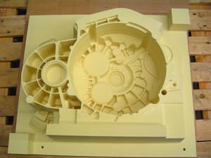 <link file:7299 download> |
| There are many tasks involved in the production of a foundry model that are often based on digital data. Sescoi’s WorkXPlore 3D would be a very useful tool. |
<link file:7300 download>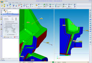 <link file:7300 download> |
| WorkXPlore 3D rapidly calculates draft angles and undercuts and colors them for display. Images: Sescoi GmbH |
<link file:7301 download>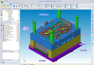 <link file:7301 download> |
| WorkXPlore 3D features a wide range of functions for adding annotations and comments. |
<link file:7302 download>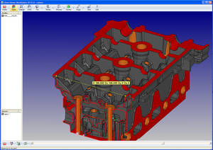 <link file:7302 download> |
| An EXE file allows users to transmit scenes to partners involved in the decision-making process even if they have not installed WorkXPlore 3D. |
<link file:7303 download> <link file:7303 download> |
| Werner Möller, "Often, WorkXPlore takes less than half the time to open a native file compared to the original CAD application." |
Nowadays, it is impossible to imagine the world of product design without 3D viewers. For product development, model construction for foundries, molds, calculations,… – whenever the full power of a CAD system is not needed, viewers come into their own. Sescoi’s WorkXPlore 3D illustrates how display and analysis capabilities help reduce time and costs.
Today, the entire process chain is founded on digital data. From the initial concept, through construction of a model or mold, to the final product, digital data are frequently used. Obviously, the person responsible for generating a first quotation needs different data and software than those required by a designer. This applies to anyone who turns concepts into concrete form: model makers and foundries as well as tool and mold makers.
For their initial calculations and operations, they do not need powerful, expensive, high functionality CAD/CAM software. A viewer tool is clearly more useful and enables users to open and visualize 2D and 3D data. Today’s viewers offer an array of functions for performing measurements and analysis, running animations, inserting notes, exchanging results online and processing documentation and publication data.
Werner Möller, Sescoi GmbH’s sales director, outlines the main benefits of a 3D viewer: Compared to a full CAD seat, a viewer software license is considerably cheaper. A viewer is also easier to use. Our WorkXPlore 3D software demonstrates this. As with all Sescoi’s software solutions, its intuitive, efficient interface ensures that users are up and running with the software fast. This reduces training time and costs. Further savings are generated by WorkXPlore 3D’s high speed import of native CAD files which often takes less than half the time to open a file compared to the original CAD application, even for very large files.
No expert knowledge needed
Ease of use is very important as users are not necessarily CAD experts. A user guide in the user’s language must be available and a choice of other languages may also be helpful. If the user has questions or needs help, the software ‘help’ is preferably context sensitive and directly accessible from the function concerned without the user having to search. Sometimes, the user even needs a printed output.
As well as these important requirements, the value of a 3D viewer is derived from its functions and features that must facilitate the user's work.
These functions include measurement, analyses, animation, annotation, documentation, assembly and publication.
Measurements on a 3D model need to be highly precise. Predefined selection modes (points, 2D objects, planes, surfaces, etc.) allow the user to obtain reliable results fast. To make the user’s work even easier, measurements can be automatically included as measurement entities anchored to characteristic points of the part. CAD/CAM expert, Werner Möller outlines WorkXPlore 3D's specialist measurement functions: Expert CAD users can recover point clusters from 3D measuring equipment or machine probes to quickly check data vis-à-vis the original CAD geometry. It is also possible to generate control point files for transmission to 3D measuring equipment or NC machines.
CAD level features
Analysis tools are a key feature of a 3D viewer. They help perform diagnostics or production preparation for 3D models. This is the point where the wheat is really separated from the chaff as these features determine a viewer's efficiency. The following functions, usually only available with more costly CAD solutions, are indicative of a very high performance level:
- High performance dynamic sectioning allows users to precisely and easily explore a part or an assembly. The dynamic reference controller allows users to control the section plane with the mouse in rotational and panning directions as well as according to a guide curve. The cross section can be made visible on the 3D model or as an isolated entity and can be extracted and exported via the DXF, DWG, etc. interfaces.
- Curvature radius and plane face analysis is a valuable tool for users enabling fast cost and production time evaluation. The coloring of elements to be analyzed is automatic. Users can insert measurement labels containing precise values for the elements selected.
- Generation of the bounding box of an object is instant and automatic. It provides information on the dimensions, volume and weight of the selected elements and can also be used to determine the optimal stock model required for manufacturing.
- Precise measurement information is available both on objects and surfaces and enables rapid calculation of volumes and areas. Complementary information such as the object name, encumbrance, number of faces, etc. is also available.
- The calculation and display of drafts and undercuts are extremely quick, even on very large parts. They are automatically colored according to the mold stripping axis. Precise draft angle values are displayed dynamically as the mouse is dragged over the surfaces. These can be inserted automatically in the 3D model.
- Automatic 3D part comparison allows real time 3D graphic display of the differences between two versions. Modifications are clearly identified by different colors to distinguish between material added and material removed. Werner Möller adds,
To use the WorkXPlore analysis functions, the two models don't even need to come from the same CAD system
Another strength of WorkXPlore 3D is its ability to access native CAD data without the need for conversion or to have the original CAD software. Data import is simple and functional. Data can be exported in IGES or WorkNC (CAM) format. Users may convert standard and native 3D model formats. The software offers a wide range of CAD interfaces (IGES, STL, URML, WorkNC geometries). As an option, WorkXPlore 3D can even be integrated with Sescoi’s WorkPLAN Enterprise custom manufacturing ERP solution in order to retrieve a part’s technical criteria to create quotations or carry out other project tasks. The technical criteria include data such as the part's dimensions, its measurements and the raw material block size, surfaces, radii and draft angles. The part data can be directly transmitted to Sescoi's system, WorkNC, enabling the workzone to be created automatically.
FRAME
Free download
Companies can test WorkXPlore 3D with their own data. Download the full version software for a test period of four weeks from Sescoi's internet sites (www.sescoi.com or directly from www.workxplore-3d.com). At the end of this four week period, continue to use WorkXPlore 3D viewer version absolutely free and for an unlimited period.