Von Christian Reul, Sebastian Esser, Frank Donsbach
1. ALLGEMEINES
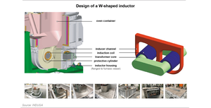
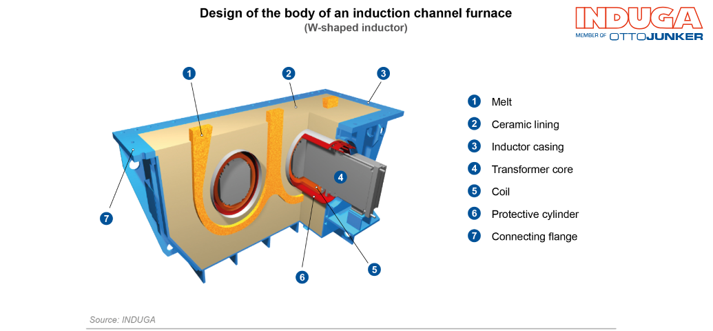
Der Rinnenofen arbeitet nach dem Prinzip eines Transformators. Dabei stellt eine Rinne mit flüssiger Schmelze die sekundäre, praktisch kurzgeschlossene Wicklung des Transformators dar. Der Kurzschlussstrom verursacht ohmsche Verluste und erhitzt so das flüssige Metall und gibt dabei seine Wärme unter mäßiger Badströmung an das beliebig gestaltbare Oberofengefäß ab. Mit diesem Prinzip lassen sich Wirkungsgrade von 80 bis 90 Prozent erzielen.
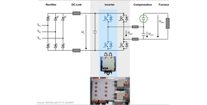
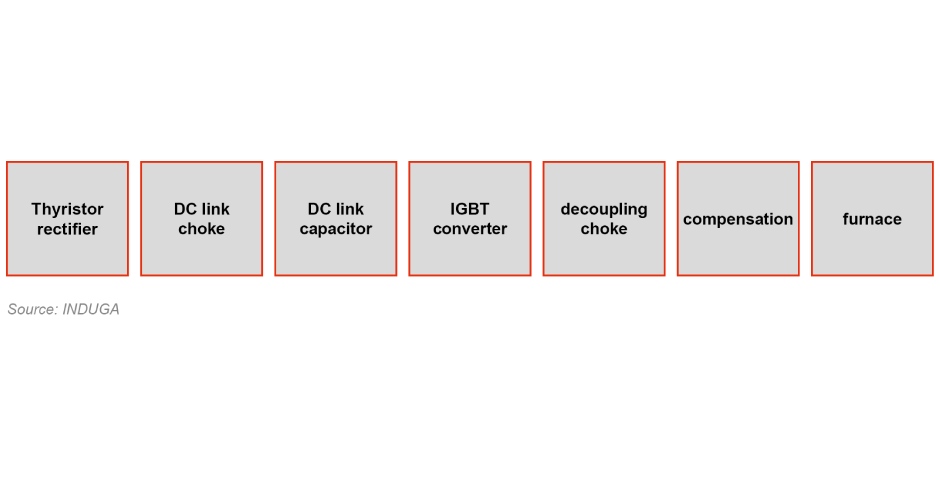
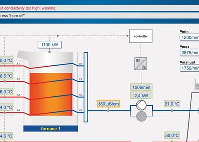
Der Oberofen kann wahlweise je nach Anwendung wannen-, trommel- oder zylinderförmig ausgeführt werden. Auch druckentleerte Mehrkammeröfen können so konzipiert werden. Die pimäre Wicklung wird an eine Leistungsversorgung angeschlossen. Diese stellt die geeignete Spannung (praktisch meist zwischen 180 und 690V) zur Verfügung und kompensiert die induktive Blindleistung des Induktors.
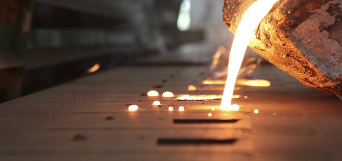
Im Unterschied zum Tiegelofen sollte der Rinnenofen mit Ausnahme weniger spezieller Anwendungsfälle nicht vollständig entleert werden und muss ständig mit flüssiger Schmelze gefüllt sein. Daher eignet er sich ideal für kontinuierliche Schmelz- und Gießprozesse ohne häufige Legierungswechsel.
Der hohe Wirkungsgrad des Rinnenofens hat ihn insbesondere für hoch leitfähige Werkstoffe, wie Kupfer, zum Standard-Schmelzaggregat gemacht. Für Kupfer und Aluminium lassen sich ca. 25% niedrigere Energieverbräuche für das Schmelzen erzielen, als dies bei Verwendung eines Tiegelofens der Fall wäre.
Da die Wärme in der Rinne selbst entsteht, ist es sehr wichtig, dass diese Wärme in ausreichendem Maße an das Oberofengefäß abgegeben wird. Deshalb strebt man eine hohe Strömungsgeschwindigkeit im Induktor an.
Bedingt durch die elektromagnetischen Lorentzkräfte [1] bilden sich im Rinnenquerschnitt intensive Strömungswirbel. Diese Strömung wird von einer durch thermische Auftriebskräfte verursachten Transitströmung überlagert, die durch die Rinne hindurchführt. Diese Transitströmung erreicht deutlich geringere Geschwindigkeiten im Vergleich zu den elektromagnetisch erzeugten Wirbeln. Dadurch ergibt sich ein sehr komplexes Strömungsverhalten, welches durch unsymmetrische Ausführung der Rinnenäste stabilisiert werden kann. Im Mittel beobachtet man eine nahezu gerichtete Strömung hin zum aufgeweiteten Rinnenast (Trompete)[1].
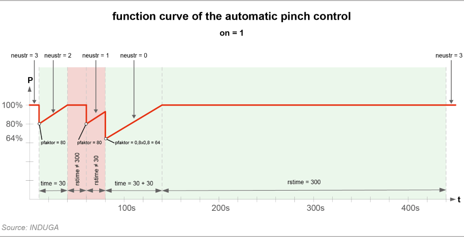
Um eine Warmhalteleistung oder eine Schmelzleistung zu realisieren, muss der Induktor ausreichend dimensioniert werden. Eine zu hohe Leistung des Induktors kann auch zur Überhitzung der Schmelze und somit der keramischen Auskleidung führen. Wenn die elektromagnetischen Kräfte zu groß werden, besteht zusätzlich die Gefahr, dass das flüssige Metall „abgeschnürt“ wird. Dadurch kann kein Strom mehr in der Rinne fließen und das elektrische Verhalten des Induktors verändert sich schlagartig – ein Vorgang der als „Pinchen“ bezeichnet wird.