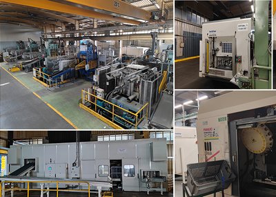
Agrati AEE srl is one of the most prestigious Italian manufacturers of die casting machines in Europe.
AGRATI AEE's production site is located in Bergamo, a few kilometres from Milan. It draws on almost 90 years of know-how, partnerships with the world's best technical partners in the fields of electronics and hydraulics, and its own technologies.
In recent years, in collaboration with the world leader in hydraulic technology Parker Hannifin, it has developed the innovative Eco Drive injection technology, a solution for optimising the die-casting process that improves both productivity and product quality.
HOW DOES THE ECO DRIVE SYSTEM WORK?
In order to better understand the EcoDrive System, we drew on the experience of Alessandro Betti, Sales Director of AGRATI AEE, who knows the dynamics and the needs of customers.
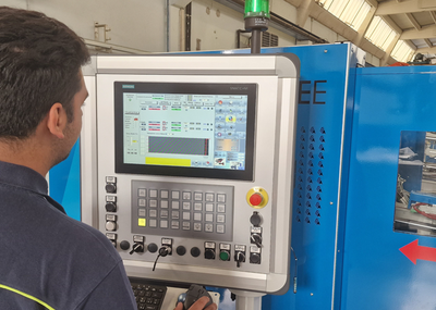
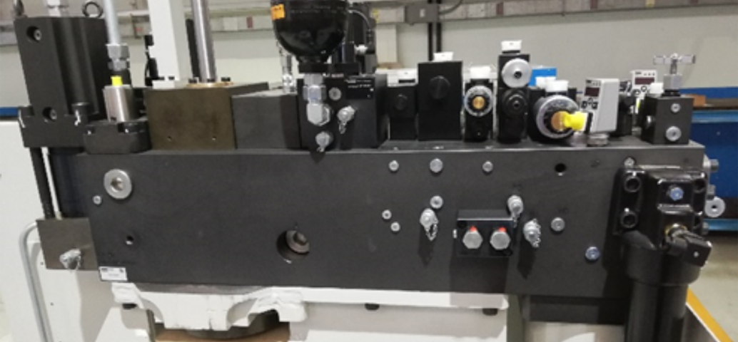
“The EcoDrive System works with the 2-way high response valves series TDP in combination with a Compax3F controller, enabling dynamics and accuracies that had not previously been achieved.
This contributes to greater productivity since rejects are reduced to an absolute minimum.
The solution keeps system pressure constant and provides protection from pressure peaks and cavitation thanks to an accumulator on rod side and a check valve. This system also extends the lifetime of all hydraulic components of the die casting machine.
Up to 20 % of energy is saved as a result of energy recovery during injection cycle”
What are the BENEFITS of the ECODRIVE injection system?
We can summarise all the advantages of the ECO DRIVE System, continues Alessandro Betti, by outlining them as follows:
a) Response times of the cylinder movements are greatly reduced;
b) Injection SPEED need is achieved with smaller valve openings;
c) ABSENCE of pressure peaks is guaranteed: the maximum pressure in the circuit is now that of the accumulator (130 bar); previously, with the intervention of the outlet brake, values of 230 bar were also reached;
d) The INCREASE of the mould front surface is guaranteed due to the absence of pressure peaks;
e) TDP lifetime is longer due to the benefits of the smaller opening;
f) Guaranteed better braking and control of the injection cylinder;
g) Reduced accumulator charging time due to oil recovery after first injection phase;
h) In the machine tank, there is now a reduction in emulsions because the injection unit discharges very few and at low pressure;
i) Reduction in the size of the injection unit drainage pipe;
j) Increased pump life due to reduced emulsions in the tank;
k) ENERGY SAVING due to reduced loading times.
Which are the injection cycles?
Here too, we can make use of explicative images, explains Alessandro Betti.
Injection cycle - first phase
All phases of the injection cylinder are performed under accumulator and controlled by the TDP valve. In the first phase, at the exit of the injection cylinder, after the controlled safety cartridge, the oil is no longer discharged into the tank, but returns to the accumulator pressure line.
Injection cycle - second phase
In the second phase, when the TDA valve (TDP in case of closed loop options) is opened, the oil accumulates in a pressure transformer which keeps the pressure on the discharge line constant, thus avoiding pressure peaks and water hammer. A small amount of oil is discharged at low pressure into the tank.
With the additional closed-loop option, 8 speed ranges with corresponding ramps and 5 pressure setting ranges can be defined.