

by GAETANO CORAGGIO. Process Engineer - MAGALDI TECHNOLOGIES, LLC
The increasing demand of customers pushes suppliers to research and develop new casting processes and technologies.
CASTING COOLING
One of the main issues in the foundry field is the casting cooling time.
An efficient casting cooling method allows foundries to increase their production volumes, also through a properly designed material handling system and a tailored-made plant arrangement. In order to gain a reliable and flexible process it is necessary to have a fine-tuning step and adjustment of casting cooling parameters. Regardless the casting process, the cooling method must be able to ensure the performance along the casting cooling curve.
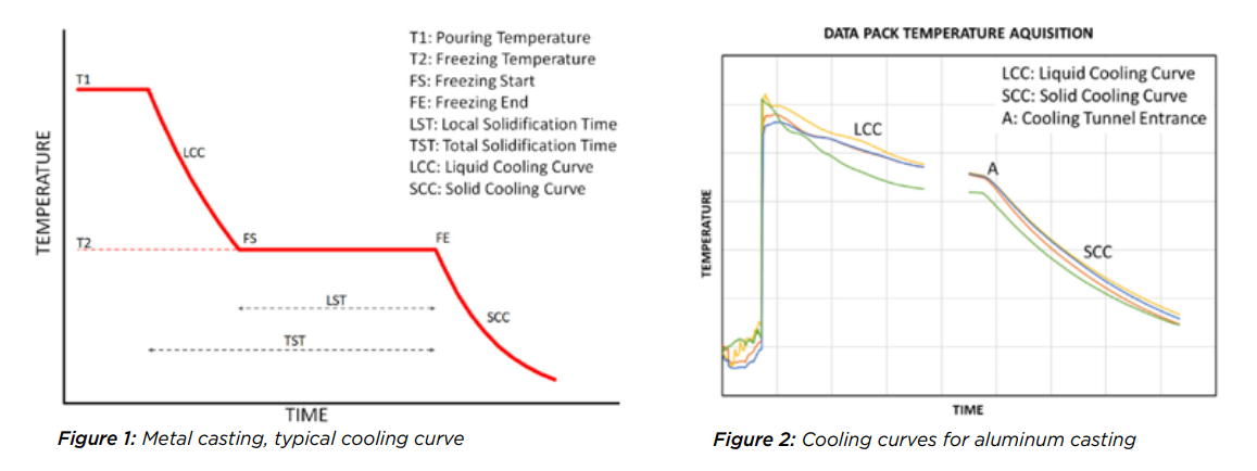
In the metal casting processes, the solidification is a phenomenon that controls several properties of the final product. In this scenario, the cooling curves control the quality of the castings. One of the most important parts of the cooling curve is the cooling rate, which affects the microstructure and properties of the castings. During the local solidification time, the material is completely converted from liquid to solid. In alloys, solidification will not occur at a given temperature value, but in a range that depends on their composition.
After solidification is over, solid cooling (ref. SCC in the Figure 1) occurs at different rates.
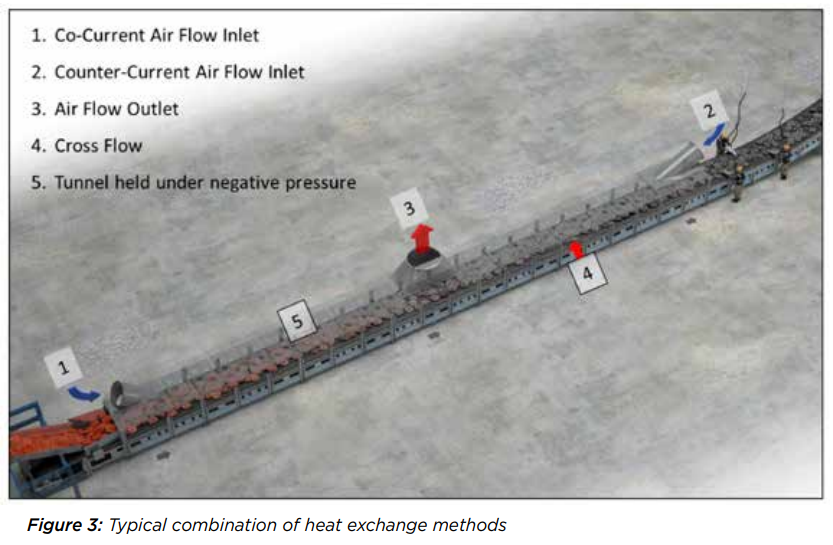
Figure 2 shows the cooling curves obtained on aluminum castings for reference. The curves were obtained with a data pack (data logger) wired to an aluminum casting with a set of thermocouples. The data logger stores the temperature trend from the casting pouring until the end of the cooling stage. The missing area is due to the disconnection of the data pack before manipulator loads the casting on the steel belt conveyor. Figure 2 shows again two cooling curves: a liquid cooling curve (LCC) and a solid cooling curve (SCC). The point “A” represents the beginning of the forced air cooling when the castings enter the castings cooler conveyor. The main purpose of the present article is to discuss the solid cooling curve (SCC).
CASTING COOLING TECHNOLOGIES
The most common technologies to perform the casting cooling process downstream the molding line are:
- Cooling drums
- Vibrating coolers
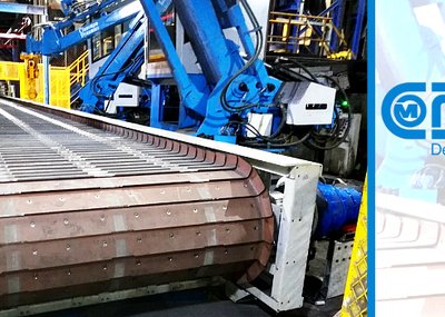
- Steel belt coolers
The steel belt coolers have multiple advantages compared to the other conventional technologies:
- Smooth castings handling with no vibrations, dust or noise.
- No relative motion between material and belt, thus no wear.
- Flexible layout arrangement, including greater inclined ramps for material lifting.
- No heavy foundations are required.
- Castings indexing according to foundry needs.
Moreover, an automated system performs a dynamic control on the process parameters, such as:
- The temperature of the castings, through a set of optical pyrometers at different points along the transportation.
- The casting ID in order to adjust the air flow rate and the steel belt speed, according to the casting type.
HEAT TRANSFER METHODS
In order to reduce the cooling time, the thermal energy has to be efficiently removed from the castings.
One of the most critical factors in the casting cooling process is the heat exchange method adopted to cool the castings down. In a parallel-flow pattern, also referred to as “co-current” flow, both the airflow and the castings enter the cooling tunnel at the same point and then moves together in the same direction. This method is not as effective because there is a large temperature gradient at the inlet of the cooling tunnel and the cooling medium cannot reach a given temperature to maximize the overall efficiency of the cooling process.
Counter-flow pattern, also referred to as “counter-current” flow, is by far the most common arrangement for heat exchange. It occurs when the airflow and the castings enter the cooling tunnel at opposite points and flow in opposite directions. The temperature gradient at the inlet of the cooling tunnel is smaller, thus reducing thermal stress of the castings, while the overall efficiency of the cooling process is maximized.
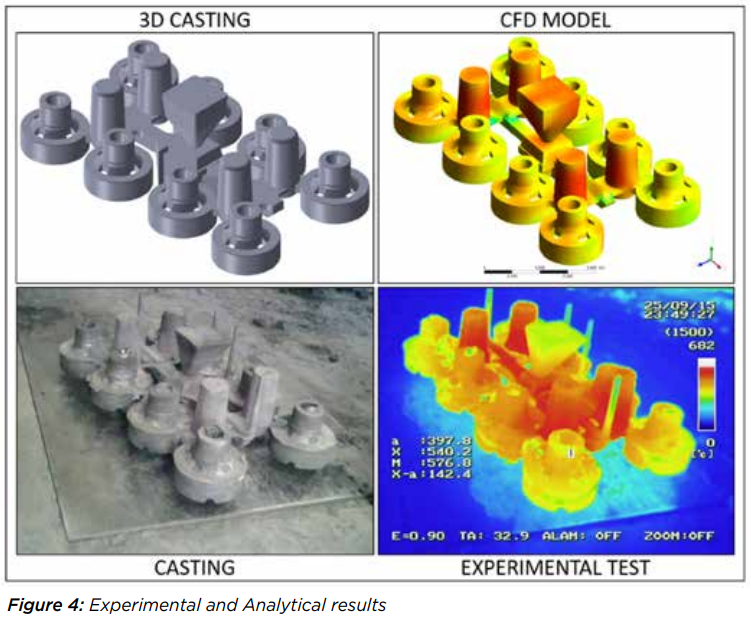
According to layout and space constraints, it is possible to adopt a combination of both heat exchange arrangements: parallelflow and counter-flow.
In addition to the co-current and counter-current air flows, a further cooling air flow, also referred to as “cross flow”, enters the system through some slots on the belt pans. Thus, the cooling rate performance is enhanced.
In this way, cooling air not only flows around the castings, but also passes through them, resulting in a more effective cooling.
Figure 3 shows a typical configuration of the cooling tunnel held under negative pressure. A stream of cooling air flows at controlled speed to avoid thermal shocks to the castings. Ambient air is forced to enter the extremities of the cooling tunnel and then it is sucked from the central hood.
CFD MODEL
In order to perform an efficient casting cooling process, the thermal properties both of air and of castings have to be thoroughly investigated. Thus, a CFD (Computational Fluid Dynamics) approach is required to implement the casting cooling simulation model. Starting from the casting 3D model, a calculation grid (mesh) is generated. Then, both the thermal properties and the boundary conditions are set in the pre-process ambient of a dedicated CFD software.
As a result, the cooling curve is finally obtained through the postprocess along with further process parameters: e.g. air speed and pressure drop in the cooling tunnel, castings and air temperature. In order to validate the above CFD analysis, an experimental test campaign can be carried out if the reference castings are available.
EXPERIMENTAL TESTS
Thanks to a specific test-rig equipped with a cooling tunnel prototype, it is possible to validate and adjust the theoretical curve obtained from the CFD analysis. A set of thermocouples welded on the tested casting is connected to a data acquisition system.
It is possible to monitor the temperature trend of that casting during the heating stage in the oven, until the end of the cooling process.
The thermocouples positions are defined according both to clients input and to critical cooling areas highlighted by the CFD analysis.
Figure 4 shows a comparison between the experimental results and the analytical once obtained through the CFD analysis.
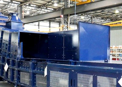
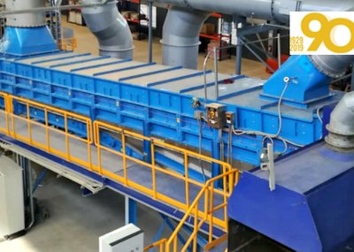
MCC® Magaldi Casting Cooler
The Magaldi Casting Cooler - MCC® - is an automated system for the transportation and cooling of castings downstream the molding lines and it can also be a valuable workstation for degating operation, avoiding the need for a further conveyor.
The MCC® system is based on the well-proven Superbelt® technology, with more than 1500 applications worldwide that overcome the drawbacks of the competing systems.
Custom-made technical solutions can be studied to solve specific problems for any severe applications.
- High mechanical dependability
- Efficient casting cooling
- Absence of vibration, dust and noise, making the MCC® a perfect working table for degating and sorting operations
- Flexible layout arrangement, including inclined ramp for material lifting
- No heavy foundations required
- Low power consumption, low spare parts requirements
- Fully integrated supervision system, for automatic and optimized operation (MISS®)

